
CAD & BIM Modeling Services
3D Data Processing for Industrial Projects
Why Choose Our 3D Modeling Team?
We focus on delivering accurate 3D data that clearly represents each project. With experience in mechanical engineering, our team works on projects ranging from MEP installations in buildings to complex equipment and production systems in industrial facilities.
Depending on the project, we create 3D models from point clouds, technical documentation, drawings, or other available project information. We work closely with the client from the start of the project to final delivery. Our models follow relevant standards and are prepared to be easy to review, manage, and edit in the required software. Our team focuses on accuracy, clear communication, and on-time delivery.
We have worked with international engineering consulting firms and global companies in the power, oil and gas, petrochemical, and water and wastewater industries. Our services support projects across European and Balkan markets.
Below are the main types of 3D data processing and applications we provide:
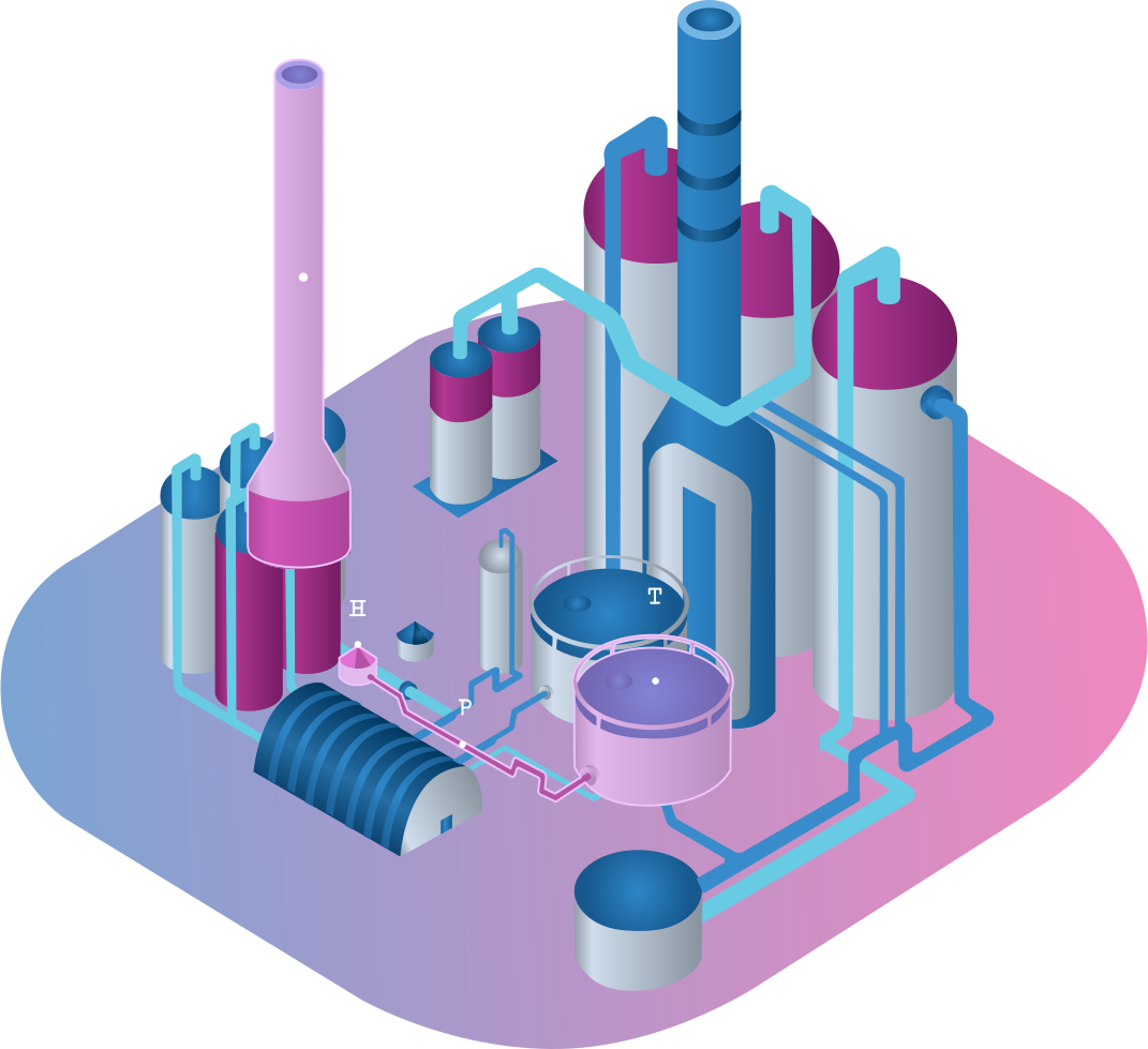
FULL 3D SUPPORT IN MECHANICAL ENGINEERING PROJECTS
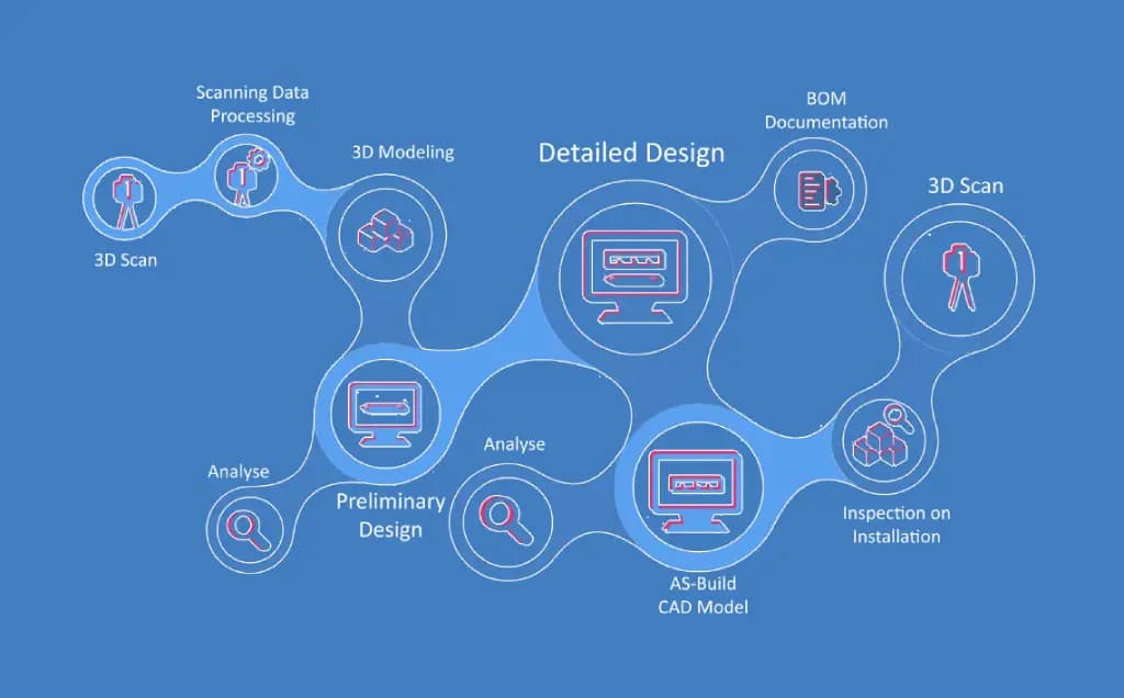
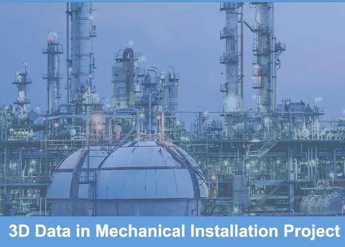
We provide complete 3D support for mechanical installation and operational projects, as well as architecture and civil engineering work. Our team creates accurate 3D models and uses modern 3D technologies during planning, design, installation, handover, and production.
•Detailed 3D models that support accurate project design and coordination.
•3D animation and simulation of activities and methods to help teams understand project planning and execution.
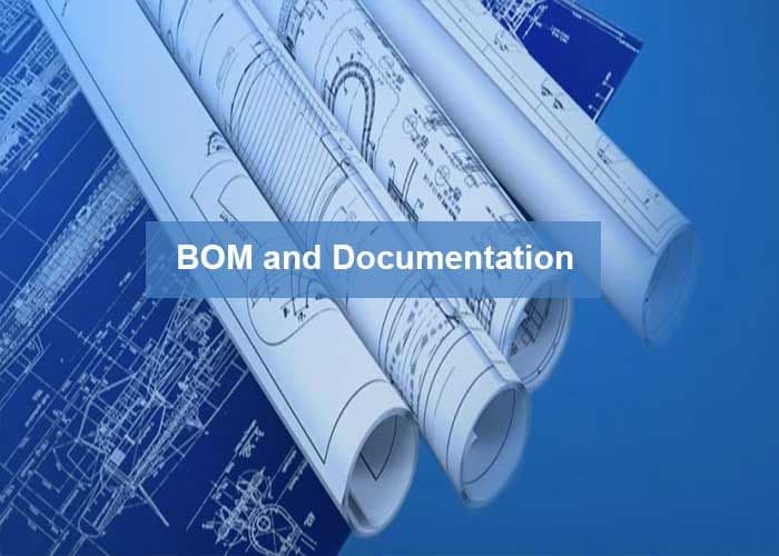
•Bill of Materials |BOM| documentation to support material planning and project management.
•As-built 3D models that show the final installed condition for future use and maintenance.
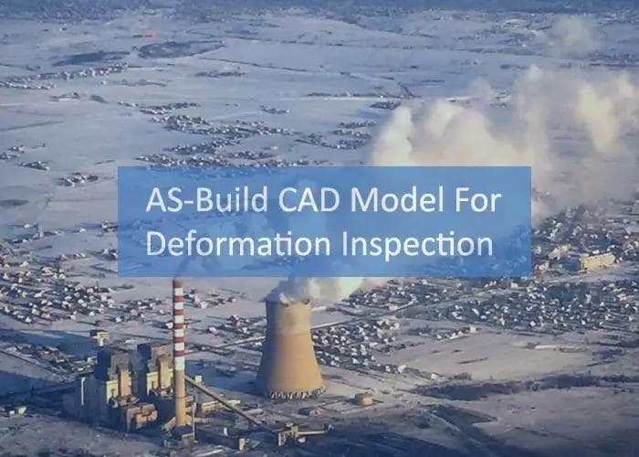
•Digital methods for installation inspection to support quality and project requirements.
Our 3D methods can support equipment upgrades, new installations, overhauls, and technical documentation. By using modern 3D technologies, we help project teams improve accuracy, reduce errors, and work more efficiently. Our solutions can be used to understand complex systems, plan installation work, improve workflows, and support accurate project execution.
We continue to improve our tools and working methods to provide reliable results for each project. Our goal is to turn project information into clear and useful 3D data that supports engineering teams from planning to final delivery.
In the posts below, you can find more information about this type of service, as well as examples from customers who have implemented these services in engineering projects.

How can I get started with your 3D support services?
To get started, simply reach out to us with your project details. Our team will discuss your needs and outline how our 3D support services can enhance your mechanical engineering projects, ensuring a smooth collaboration.
Can your 3D models be integrated with other software?
Yes, our 3D models can be exported in various formats compatible with popular engineering software such as AutoCAD, SolidWorks, and Revit, facilitating integration with your existing workflows.
In which industries do you apply your 3D support services?
Our 3D support services are applicable across various industries, including manufacturing, construction, oil and gas, automotive, and aerospace, where precise modeling and visualization are crucial for project success.
How do you ensure the accuracy of your 3D models?
We ensure the accuracy of our 3D models through rigorous data collection methods, advanced modeling techniques, and ongoing quality assurance processes. Our team employs state-of-the-art tools and software to maintain high precision standards.
What is the typical turnaround time for creating 3D models?
The turnaround time for creating 3D models depends on the project's complexity, size, and specific requirements. We work closely with clients to establish timelines that align with their project goals and deadlines.
Do you offer training or support for using your 3D modeling tools?
Yes, we provide training and support for our clients to ensure they can effectively utilize our 3D modeling tools and software. Our team is available to assist with any questions or challenges that may arise.
PDMS - Plant Design Management System and BIM - Building Information Modeling 3D Models
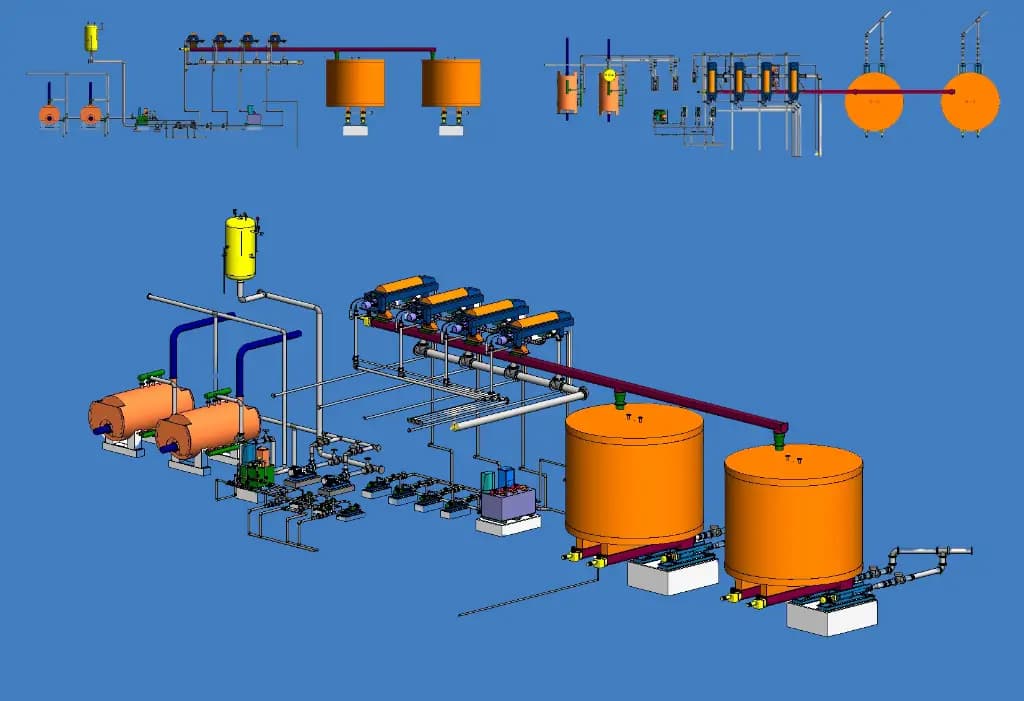
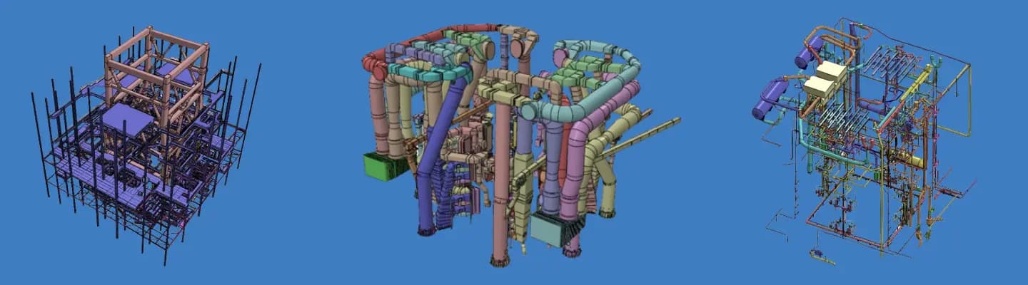
We create PDMS |Plant Design Management System| 3D models for plant and process engineering projects. PDMS is used to design complex industrial facilities such as oil and gas plants, chemical plants, power plants, and water treatment facilities. These 3D models can include piping, equipment, structures, electrical systems, and instrumentation, giving engineering teams a clear digital view of the complete plant.
•Complete Plant Design:more ▼
•Complete Plant Information:Includes equipment locations, piping layouts, structures, supports, and other important plant components.
•Team Collaboration:Allows engineers and designers from different disciplines to work with the same project data and coordinate their work.
•Clash Detection:Helps identify clashes between piping, equipment, structures, and other systems before installation or construction.
•Data Integration:PDMS data can be used with other engineering and design tools to support data exchange between different project stages.
•Technical Documentation:Detailed drawings, reports, and project information can be created from the 3D model to support engineering and project documentation.
•PDMS 3D Models:Support the design, construction, operation, and maintenance of complex industrial facilities.
We create PDMS 3D models with different levels of information, from basic non-intelligent models to fully intelligent models, depending on the needs of the project.
•Levels of Intelligence:more ▼
•Level 1 Non-Intelligent PDMS Models:Basic 3D models without logical grouping or tagging, mainly used for visualization or specific data imports.
•Level 2 Basic Non-Intelligent PDMS Models:3D objects are organized into logical groups and individual names, providing a basic model structure.
•Level 3 Partially Intelligent PDMS Models:3D objects are grouped and include basic tagging and project information.
•Level 4 Enhanced Partially Intelligent PDMS Models:Piping, equipment, structures, and other objects are organized with standard tagging and additional project information.
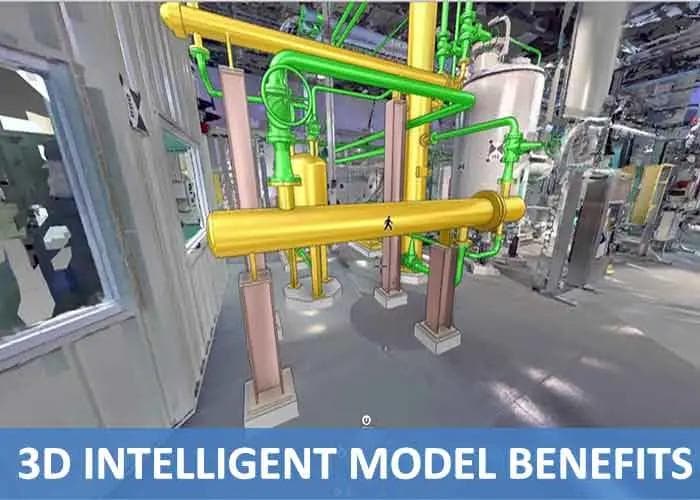
•Level 5 Fully Intelligent PDMS Models:Detailed models with complete tagging, naming, and engineering information for use across different project stages.
Our PDMS 3D models can also include important plant areas and routing information such as escape routes, hazardous area classification zones, maintenance and operation areas, and pipeline right of way |ROW|. This information helps create practical 3D models that support engineering, operation, maintenance, and safety requirements.
•Software Used for PDMS 3D:more ▼
•AVEVA PDMS:Used for 3D plant design in industries such as oil and gas, petrochemicals, power generation, and process engineering.
•Autodesk Revit:Used for BIM modeling in architecture, engineering, construction, and MEP projects.
•LOD Variations for PDMS 3D:more ▼
•LOD 100:Conceptual models used for early project planning and design studies.
•LOD 200:Basic design models used for space planning and early project coordination.
•LOD 300:Detailed models used for design coordination and clash detection.
•LOD 400:Detailed models with information required for fabrication and assembly.
•LOD 500:As-built models that represent the final installed condition of the project.
•Connectivity with BIM 3D:more ▼
•Data Exchange:PDMS and BIM data can be exchanged between different software tools to support accurate and consistent project information.
•Connected Workflows:PDMS and BIM models can work together to support design, construction, installation, and facility management.
•Clash Detection and Coordination:Combined models help project teams identify and solve clashes between different systems and components.
•3D Visualization:PDMS and BIM models can be combined to provide a clear 3D view of the project for review, coordination, and simulation.
•Facility Management:BIM models with PDMS data can provide useful information for operation, maintenance, and future facility changes.
Connecting PDMS 3D models with BIM helps project teams work with accurate and organized information throughout the project. This improves coordination between different disciplines and supports design, construction, installation, operation, and maintenance.
In the posts below, you can find more information about this type of service, as well as examples from customers who have implemented these services in engineering projects.
What is BIM, and how does it integrate with PDMS?
BIM, or Building Information Modeling, is a digital representation of a building's physical and functional characteristics. Integrating BIM with PDMS enables better coordination, enhances data sharing, and supports more effective project management across the lifecycle of industrial and plant projects.
What is PDMS, and how does it benefit plant design?
PDMS, or Plant Design Management System, is a 3D modeling software primarily used in the plant and process industries, such as oil and gas, chemical, and water treatment facilities. It allows engineers to create comprehensive 3D models of plant systems, including piping, equipment, and electrical systems, ensuring accurate, safe, and efficient plant design.
Can PDMS models include safety features like escape routes and hazardous zones?
Yes, our PDMS models can include critical safety features such as escape routes, hazardous area classification zones, maintenance zones, and pipeline right-of-way (ROW). These features help ensure that the models are not only detailed but also aligned with industry safety standards.
What is the difference between intelligent and non-intelligent PDMS models?
Intelligent PDMS models contain metadata and embedded information, making them useful for simulations, analysis, and operational planning. Non-intelligent models, on the other hand, are basic 3D representations without additional data, primarily used for visualization purposes.
What is LOD, and how does it apply to PDMS models?
LOD, or Level of Detail, refers to the amount of information contained within a model. Our PDMS models offer various LODs, from basic to highly detailed, depending on the client’s requirements and the project's complexity, ensuring optimal balance between model detail and project scope.
Can you tailor PDMS models to specific industry standards and client requirements?
Yes, we customize our PDMS models to align with specific industry standards and individual client needs. This includes adapting models to comply with local regulations, incorporating client-specific safety and operational zones, and ensuring precise spatial configurations.
How are PDMS models used in different stages of a project?
PDMS models are used throughout the project lifecycle, from initial planning and design through installation and operation. They help in visualizing complex systems, assessing spatial requirements, planning escape routes, and ensuring compliance with safety standards, thus enhancing project coordination and management.
CAD & AS-BUILT 3D Modeling Services
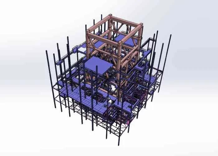
We provide CAD and as-built 3D modeling services for mechanical engineering and industrial projects. Our work ranges from simple CAD models built from basic shapes to detailed as-built 3D models created from point cloud data.
•CAD Models from Simple Primitives:more ▼
Each project has different needs. We can create CAD models using simple geometric shapes such as cubes, cylinders, and spheres to represent parts, machines, systems, or complete industrial facilities. These models can provide a clear starting point for project planning, design, and engineering work. Using software such as AutoCAD and SolidWorks, we create accurate and practical models that are easy to use during later project stages.
•AS-BUILT 3D Models from Point Cloud:more ▼
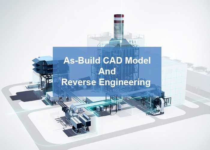
For more detailed projects, we create as-built 3D models that show the existing condition of structures, equipment, and industrial facilities. 3D laser scanning is used to capture detailed point cloud data from the real environment. We process this data with software such as Autodesk ReCap and Leica Cyclone and use it as the basis for accurate 3D modeling. These models support documentation, maintenance, inspections, retrofit work, and future project planning.
•Integration & Hybrid Modeling:more ▼
We can also combine simple CAD geometry with detailed as-built 3D models. This approach allows us to use basic geometry where high detail is not required and point cloud data where greater accuracy is needed. The result is a practical 3D model built around the needs of the project.
•Applications and Benefits:more ▼
Our CAD and as-built 3D models can support:
•Project preparation and design
•Maintenance and inspection planning
•Retrofit and renovation projects
•Technical documentation and project records
Our CAD and as-built 3D modeling services help project teams work with accurate and clear project information. The models can support better planning, easier communication, and reliable engineering decisions from the start of the project to final delivery.
In the posts below, you can find more information about this type of service, as well as examples from customers who have implemented these services in engineering projects.
What software do you use to create CAD and AS-BUILT models?
We use leading industry software such as AutoCAD, Revit, SolidWorks, and specialized point cloud processing software to ensure that our models are compatible with various platforms and meet client requirements.
What types of CAD models can you create?
We create CAD models ranging from simple geometric primitives to complex, detailed representations based on project requirements. Our CAD modeling services can be customized for various applications, from basic design concepts to intricate mechanical components and assemblies.
What is the difference between CAD models and AS-BUILT 3D models?
CAD models are typically created from scratch using design specifications, while AS-BUILT 3D models are generated from actual point cloud data captured from the physical site. AS-BUILT models reflect the real-world conditions of a project, making them ideal for documenting existing structures or installations.
How are AS-BUILT models created from point cloud data?
AS-BUILT models are created by capturing point cloud data of the existing environment using laser scanning. This data is then processed to create a precise 3D model that accurately represents the current state of the structure or installation, allowing for detailed analysis and planning.
What is hybrid modeling, and when is it used?
Hybrid modeling combines CAD and AS-BUILT data to create a comprehensive model that reflects both design specifications and real-world conditions. It’s particularly useful in retrofit or upgrade projects, where new components need to fit seamlessly within existing structures.
How accurate are the AS-BUILT 3D models created from point clouds?
Our AS-BUILT models have high accuracy, typically within a tolerance of ±1mm between the scanned object and the resulting point cloud. For final 3D models, accuracy can be tailored to meet specific project requirements, ranging from ±1mm to ±1cm, depending on client needs.